Note
Access to this page requires authorization. You can try signing in or changing directories.
Access to this page requires authorization. You can try changing directories.
The event processing editor is a no-code experience in which you drag items to design processing logic for event data. This article describes how to use the editor to design your processing logic.
Note
Enhanced capabilities are enabled by default when you create eventstreams. If you have eventstreams that you created via standard capabilities, those eventstreams will continue to work. You can still edit and use them as usual. We recommend that you create a new eventstream to replace standard eventstreams so that you can take advantage of additional capabilities and benefits of enhanced eventstreams.
Prerequisites
- Access to a workspace in the Microsoft Fabric capacity license mode or the trial license mode with Contributor or higher permissions.
Design event processing by using the editor
To perform processing operations on your data streams by using a no-code editor, follow these steps:
Select Edit on the ribbon if you aren't already in Edit mode. Ensure that the upstream node for the connected operations has a schema.

To insert an event processing operator between the stream node and the destination in Edit mode, you can use one of the following two methods:
Insert the operator directly from the connection line. Hover over the connection line and then select the + button. A dropdown menu appears on the connection line, and you can select an operator from this menu.

Insert the operator from the ribbon menu or canvas:
On the ribbon, you can select an operator from the Transform events menu.

Alternatively, you can hover over one of the nodes and then select the + button if you deleted the connection line. A dropdown menu appears next to that node, and you can select an operator from this menu.

After you insert the operator, you need to reconnect these nodes. Hover over the left edge of the stream node, and then drag the green circle to connect it to the Manage fields operator node. Follow the same process to connect the Manage fields operator node to your destination.

Select the Manage fields operator node. On the Manage fields configuration pane, select the fields that you want to use for output. If you want to add all fields, select Add all fields.
You can also add a new field by using the built-in functions to aggregate the data from upstream. Currently, the supported built-in functions are string functions, date and time functions, and mathematical functions. To find them, search for built-in.

After you configure the Manage fields operator, select Refresh to validate the test result that this operator produces.

If you have any configuration errors, they appear on the Authoring errors tab on the lower pane.

If your test result looks correct, select Publish to save the event processing logic and return to Live view.

After you complete the preceding steps, you can visualize how your eventstream starts streaming and processing data in Live view.


Transform data by using the editor
You can use the event processing editor (the canvas in Edit mode) to transform data into various destinations. Enter Edit mode to design stream processing operations for your data streams.

Edit mode includes a canvas and lower pane where you can:
- Build the transformation logic for event data by dragging.
- Preview the test result in each of the processing nodes from beginning to end.
- Discover any authoring errors within the processing nodes.
Editor layout
The event processing editor consists of three sections numbered in the following image.

On the pane that contains the ribbon menu and canvas, you design your data transformation logic by selecting an operator (from the Transform events menu) and connecting the stream and the destination nodes via the newly created operator node. You can drag connecting lines or select and delete connections.
On the right editing pane, you configure the selected node or view the stream name.
On the lower pane, you preview the test result in a selected node by using the Test result tab. The Authoring errors tab lists any incomplete or incorrect configuration in the operation nodes.
Supported node types and examples
Here are the destination types that support adding operators before ingestion:
- Lakehouse
- Eventhouse (event processing before ingestion)
- Derived stream
- Activator
Note
For destinations that don't support the addition of a pre-ingestion operator, you can first add a derived stream as the output of your operator. Then, append your intended destination to this derived stream.

The event processor in a lakehouse and a KQL database allows you to process your data before it's ingested into your destination.
Prerequisites
- Access to a workspace in the Microsoft Fabric capacity license mode or the trial license mode with Contributor or higher permissions.
- Access to a workspace with Contributor or higher permissions where your lakehouse or KQL database is located.
Design event processing by using the editor
On the right pane, add a Lakehouse destination and enter the necessary parameters. For detailed instructions, see Add and manage a destination in an eventstream.
Select Open event processor.

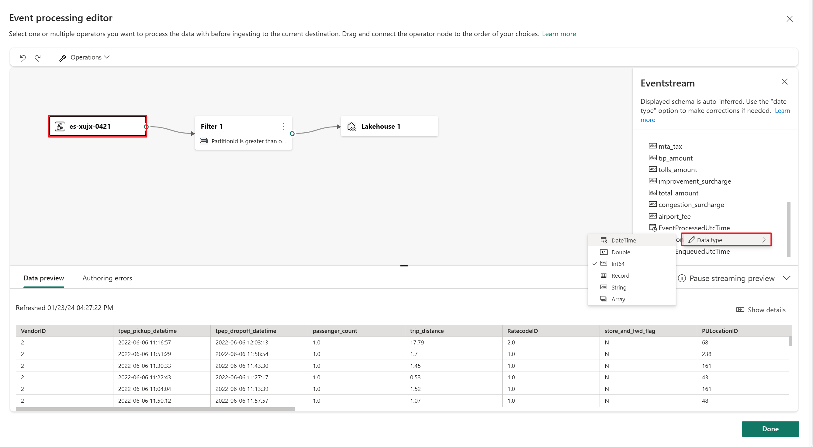
On the canvas of the event processing editor, select the eventstream node. You can preview the data schema or change the data type on the Eventstream pane.
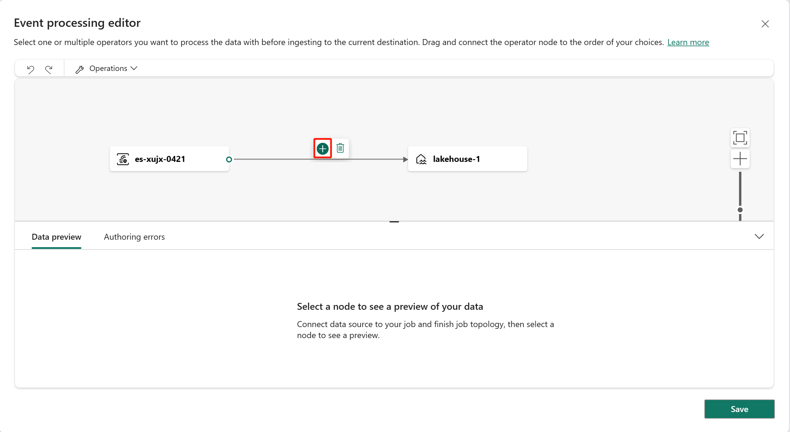
To insert an event processing operator between this eventstream and the destination in the event processing editor, you can use one of the following two methods:
Insert the operator directly from the connection line. Hover over the connection line and then select the + button. A dropdown menu appears on the connection line, and you can select an operator from this menu.
Insert the operator from the ribbon menu or canvas:
On the ribbon, you can select an operator from the Operations menu.

Alternatively, you can hover over one of the nodes and then select the + button if you deleted the connection line. A dropdown menu appears next to that node, and you can select an operator from this menu.

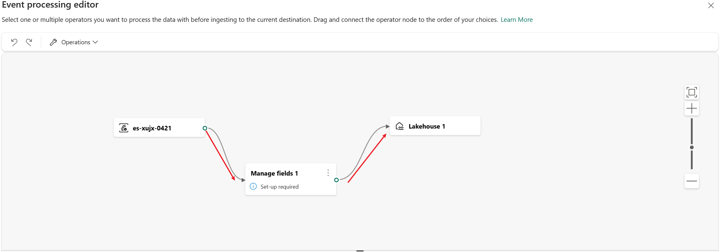
You need to reconnect the nodes. Hover over the left edge of the eventstream node, and then drag the green circle to connect it to the Manage fields operator node. Follow the same process to connect the Manage fields operator node to the Lakehouse node.
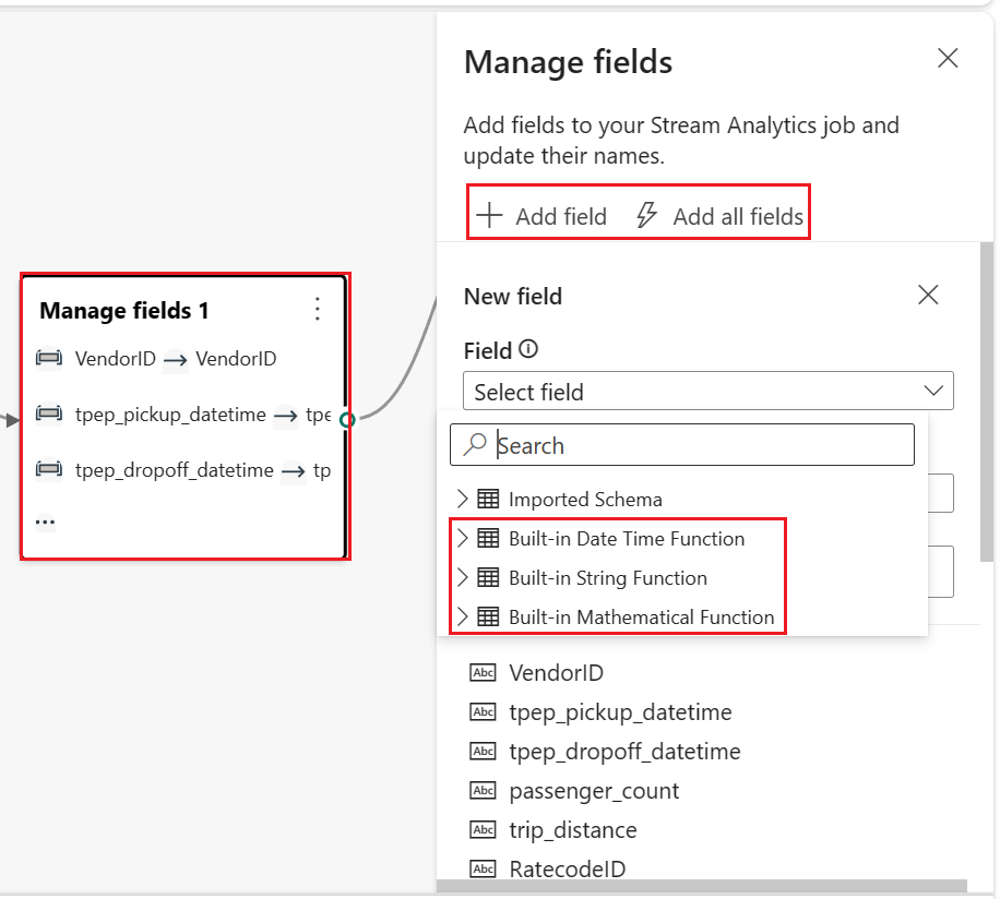
Select the Manage fields operator node. On the Manage fields configuration pane, select the fields that you want to use for output. If you want to add all fields, select Add all fields.
You can also add a new field by using the built-in functions to aggregate the data from upstream. Currently, the supported built-in functions are string functions, date and time functions, and mathematical functions. To find them, search for built-in.
After you configure the Manage fields operator, select Refresh static preview to preview the data that this operator produces.

If you have any configuration errors, they appear on the Authoring errors tab on the lower pane.
If your previewed data looks correct, select Done to save the event processing logic and return to the configuration details for the lakehouse destination.
Select Add to complete the creation of your lakehouse destination.


Transform data by using the editor
You can use the event processing editor to transform the data that you're ingesting into a lakehouse destination. When you configure your lakehouse destination, you find the Open event processor button on the pane for configuring a Lakehouse destination.

Selecting Open event processor opens the event processing editor. The editor includes a canvas and lower pane where you can:
- Build the transformation logic for event data by dragging.
- Preview the data in each of the processing nodes from beginning to end.
- Discover any authoring errors within the processing nodes.
The pane's layout is like the main editor. It consists of three sections numbered in the following image.

On the pane that contains the canvas with the diagram view, you can design your data transformation logic by selecting an operator from the Operations menu. Then, connect the eventstream and the destination nodes via the newly created operator node. You can drag connecting lines or select and delete connections.
On the right editing pane, you configure the selected operation node or view the schema of the eventstream and destination.
On the lower pane, you preview the data in a selected node by using the Data preview tab. The Authoring errors tab lists any incomplete or incorrect configuration in the operation nodes.
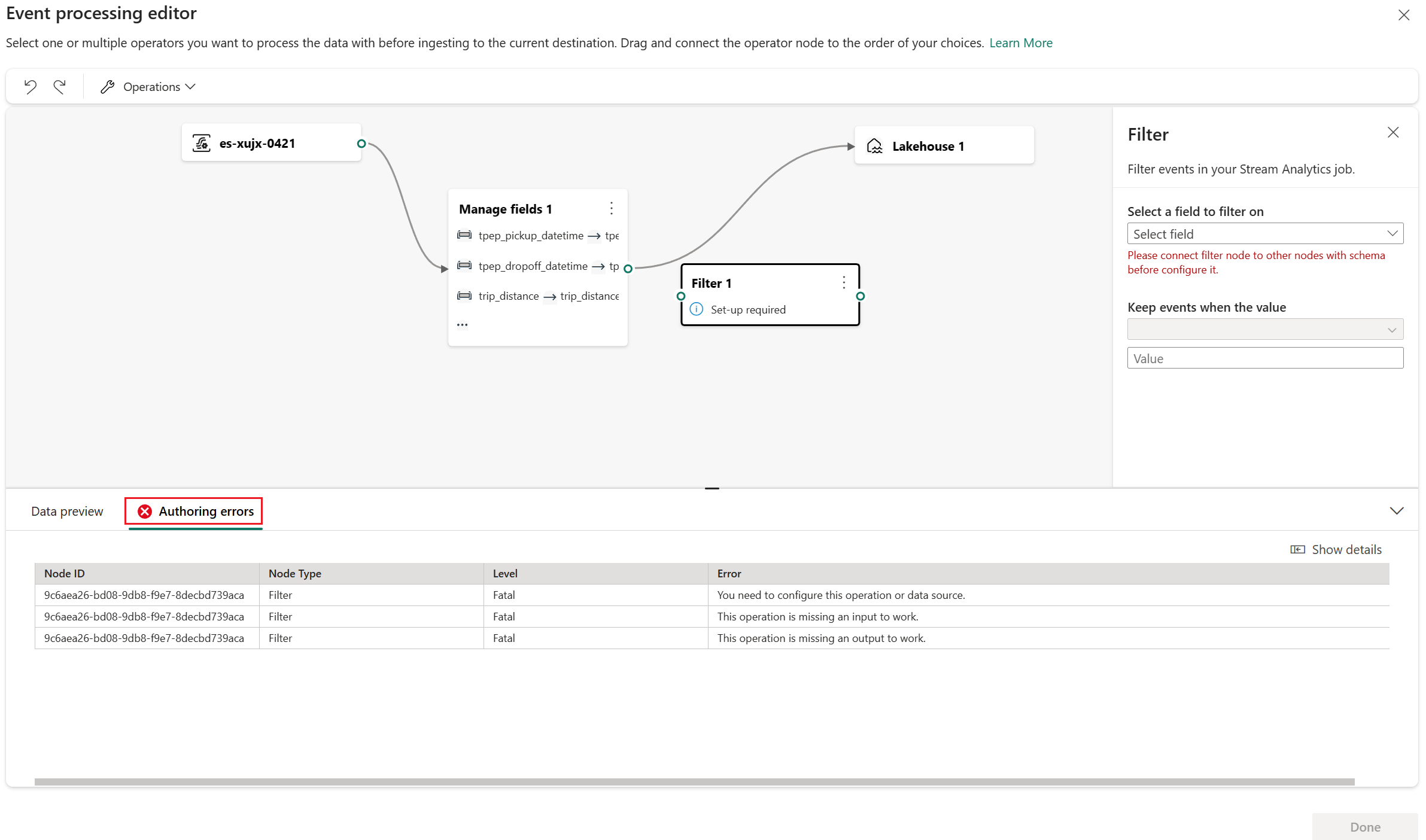
Authoring errors
Authoring errors are errors that occur in the event processing editor due to incomplete or incorrect configuration of the operation nodes. They help you find and fix potential problems.
Each authoring error has four columns:
- Node ID: Indicates the ID of the operation node where the authoring error occurred.
- Node type: Indicates the type of the operation node where the authoring error occurred.
- Level: Indicates the severity of the authoring error. There are two levels, Fatal and Information. A fatal-level authoring error means that the event processing editor has serious problems and can't be saved or run. An information-level authoring error means that the event processing editor has some tips or suggestions that can help you optimize or improve it.
- Error: Briefly describes the cause and impact of the authoring error. You can select the Show details tab to see details.
Because an eventstream and an eventhouse support different data types, the process of converting a data type might generate authoring errors.
The following table shows the results of data type conversion from an eventstream to an eventhouse. The columns represent the data types that the eventstream supports. The rows represent the data types that the eventhouse supports. The cells indicate the conversion results, which can be one of these three symbols:
✔️ Indicates successful conversion with no errors or warnings.
❌ Indicates that conversion is impossible, which generates a fatal-level authoring error. The error message is similar to: "The data type "{1}" for the column "{0}" doesn't match the expected type "{2}" in the selected KQL table, and can't be autoconverted."
⚠️ Indicates that conversion is possible but inaccurate, which generates an information-level authoring error. The error message is similar to: "The data type "{1}" for the column "{0}" doesn't exactly match the expected type "{2}" in the selected KQL table. It's autoconverted to "{2}"."
| string | bool | datetime | dynamic | guid | int | long | real | timespan | decimal | |
|---|---|---|---|---|---|---|---|---|---|---|
| Int64 | ❌ | ❌ | ❌ | ✔️ | ❌ | ⚠️ | ✔️ | ⚠️ | ❌ | ✔️ |
| Double | ❌ | ❌ | ❌ | ✔️ | ❌ | ❌ | ❌ | ⚠️ | ❌ | ⚠️ |
| String | ✔️ | ❌ | ❌ | ✔️ | ❌ | ❌ | ❌ | ❌ | ❌ | ❌ |
| Datetime | ⚠️ | ❌ | ✔️ | ✔️ | ❌ | ❌ | ❌ | ❌ | ❌ | ❌ |
| Record | ⚠️ | ❌ | ❌ | ✔️ | ❌ | ❌ | ❌ | ❌ | ❌ | ❌ |
| Array | ⚠️ | ❌ | ❌ | ✔️ | ❌ | ❌ | ❌ | ❌ | ❌ | ❌ |
As you can see from the table, some data type conversions are successful, such as string to string. These conversions don't generate any authoring errors, and they don't affect the operation of the event processing editor.
Some data type conversions are impossible, such as integer to string. These conversions generate fatal-level authoring errors and cause the event processing editor to fail the saving process. To avoid these errors, you need to change your data type in your eventstream or in your KQL table.
Some data type conversions are possible but not precise, such as integer to real. These conversions generate information-level authoring errors that indicate the mismatch between data types and the automatic conversion results. These conversions might cause your data to lose precision or structure. You can choose whether to ignore these errors or modify your data type (in your eventstream or KQL table) to optimize the event processing editor.
Transform event data by using operators
The event processing editor provides seven transformation operators that you can use to transform your event data according to your business needs.

Aggregate
Use the Aggregate transformation to calculate an aggregation (Sum, Minimum, Maximum, or Average) every time a new event occurs over a period of time. This operation also allows for the renaming of these calculated columns, along with filtering or slicing the aggregation based on other dimensions in your data. You can have one or more aggregations in the same transformation.
If you select this operator type, enter the following information:
- Operator name: Specify the name of the aggregation operation.
- Add aggregate function: Add one or more aggregations in the aggregate operation.
- Type: Select an aggregation type. The choices are Sum, Minimum, Maximum, and Average.
- Field: Select the column to process.
- Name: Define a name for this aggregation function.
- Partition by: Select a column to group the aggregation.
- Aggregate values within the last: Specify a time window for aggregation. The default is 5 seconds.

Expand
Use the Expand transformation to create a new row for each value within an array. You can select Create row for missing/empty array or Don't create row for missing/empty array.

Filter
Use the Filter transformation to filter events based on the value of a field in the input. Depending on the data type (number or text), the transformation keeps the values that match the selected condition, such as is null or is not null.
Group by
Use the Group by transformation to calculate aggregations across all events within a certain time window. You can group by the values in one or more fields. It's like the Aggregate transformation in that it allows for the renaming of columns, but it provides more options for aggregation and includes more complex options for time windows. Like Aggregate, you can add more than one aggregation per transformation.
The aggregations available in the transformation are:
- Average
- Count
- Maximum
- Minimum
- Percentile (continuous and discrete)
- Standard deviation
- Sum
- Variance
In time-streaming scenarios, performing operations on the data contained in temporal windows is a common pattern. The event processing editor supports windowing functions, which are integrated with the Group by operator. You can define them in the settings of this operator.

Manage fields
Use the Manage fields transformation to add, remove, change the data type of, or rename fields coming in from an input or another transformation. The pane for this transformation's settings gives you the option of adding a new field (by selecting Add field), adding multiple fields, or adding all fields at once.

You can also add a new field by using the built-in functions to aggregate the data from upstream. Currently, the supported built-in functions are string functions, date and time functions, and mathematical functions. To find them, search for built-in.

The following table shows the results of changing the data type by using Manage fields. The columns represent original data types, and the rows represent target data types. In the table:
- ✔️ Means that the data type can be converted directly. The option for the target data type appears in the dropdown list.
- ❌ Means that the data type can't be converted. The option for the target data type doesn't appear in the dropdown list.
- ⚠️ Means that the data type can be converted, but it needs to meet certain conditions. One condition might be that the string format must conform to the requirements of the target data type. For example, when you're converting from a string to an integer, the string needs to be a valid integer form, such as
123(notabc).
| Int64 | Double | String | Datetime | Record | Array | |
|---|---|---|---|---|---|---|
| Int64 | ✔️ | ✔️ | ✔️ | ❌ | ❌ | ❌ |
| Double | ✔️ | ✔️ | ✔️ | ❌ | ❌ | ❌ |
| String | ⚠️ | ⚠️ | ✔️ | ⚠️ | ❌ | ❌ |
| Datetime | ❌ | ❌ | ✔️ | ✔️ | ❌ | ❌ |
| Record | ❌ | ❌ | ✔️ | ❌ | ✔️ | ❌ |
| Array | ❌ | ❌ | ✔️ | ❌ | ❌ | ✔️ |
Union
Use the Union transformation to connect two or more nodes and to add events that have shared fields (with the same name and data type) into one table. Fields that don't match are dropped and not included in the output.
Join
Use the Join transformation to combine events from two inputs based on the field pairs that you select. If you don't select a field pair, the join is based on time by default. The default is what makes this transformation different from a batch one.
As with regular joins, you have options for your join logic:
- Inner join: Include only records from both tables where the pair matches.
- Left outer join: Include all records from the first (left) table and only the records from the second table that match the pair of fields. If there's no match, the fields from the second input are blank.