Note
Access to this page requires authorization. You can try signing in or changing directories.
Access to this page requires authorization. You can try changing directories.
The hub-and-spoke topology is a common network architecture pattern in Azure that consolidates network resources and centralizes network services. This topology provides network connectivity and security to virtual networks deployed across different subscriptions or tenants.
You can implement hub-and-spoke architectures in two ways:
- Self-managed hub-and-spoke (traditional): You maintain full control over the hub virtual networks and routing configuration.
- Virtual WAN: Microsoft manages the hub virtual networks and simplifies administration through features like routing intent and routing policies.
This article focuses on self-managed hub-and-spoke topologies where you have full visibility and control over the hub virtual network and Azure Firewall deployment.
You can reduce the administration overhead of a self-managed hub-and-spoke implementation by using Azure Virtual Network Manager (AVNM). AVNM can automate the configuration of Azure Route Tables, but the overall design and techniques don't change compared to the manual approach. The contents of this article apply whether you use AVNM or manually configure your self-managed hub-and-spoke topology.
An alternative to Azure Route Tables in the spoke virtual networks is injecting routes into subnets with Azure Route Server, as documented in Default route injection in spoke virtual networks. However, this pattern isn't commonly used due to the complexity that can arise from the interaction between Azure Route Server and VPN or ExpressRoute virtual network gateways.
In a self-managed hub-and-spoke setup:
- Hub: A virtual network that serves as the central connectivity point to your on-premises network through VPN, ExpressRoute, or Software-Defined Wide Area Network (SD-WAN). Network security devices like firewalls are deployed in the hub virtual network.
- Spokes: Virtual networks that peer with the hub and host your workloads.
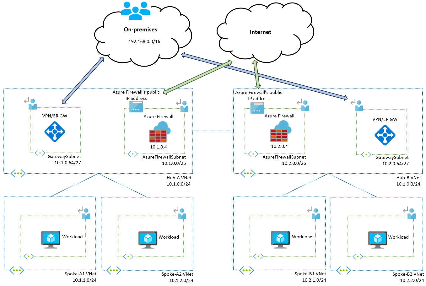
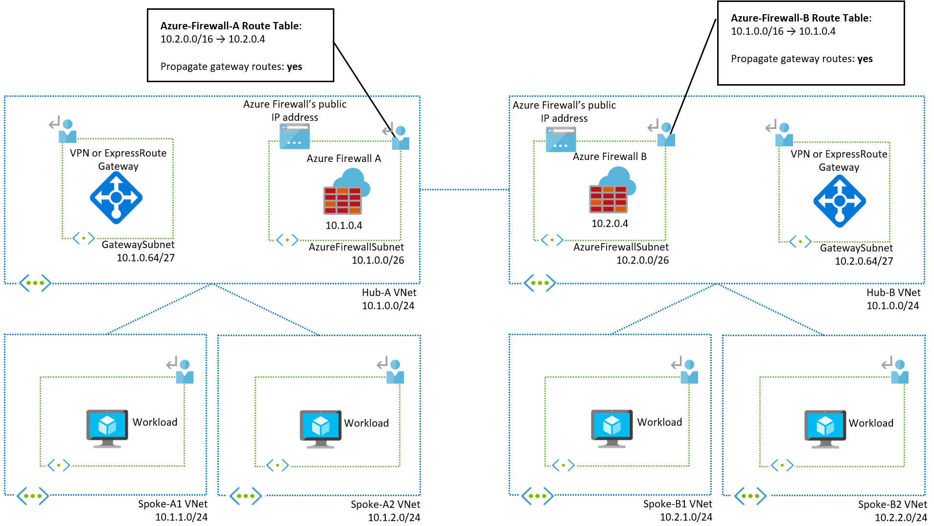
For workloads spread across multiple regions, you typically deploy one hub per region to aggregate traffic from the spokes in that region. The following diagram shows a two-region self-managed hub-and-spoke architecture with two spoke virtual networks in each region:
Single-region hub-and-spoke architecture
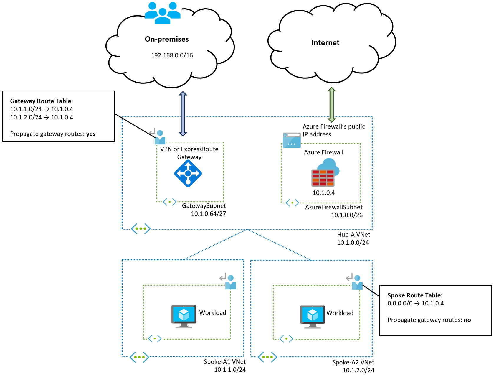
To understand the multi-region design, you first need to understand the single-region concepts. The following diagram shows the routing table configuration for the first region:
Consider the routing requirements for each potential traffic flow in the single-region design to understand the user-defined route configuration:
- Spoke-to-spoke traffic: Spokes aren't peered to each other, and virtual network peering isn't transitive. Each spoke knows how to route to the hub virtual network by default, but not to other spokes. A route for
0.0.0.0/0applied to all spoke subnets covers spoke-to-spoke traffic. - Spoke-to-internet traffic: The
0.0.0.0/0route in the spoke route table also covers traffic sent to the public internet. This route overwrites the system route included in public subnets by default. For more information, see Default outbound access in Azure. - Internet-to-spoke traffic: Traffic from the internet to the spoke usually goes through Azure Firewall first. Azure Firewall has Destination Network Address Translation (DNAT) rules configured, which also translates the source IP address (Source Network Address Translation or SNAT). The spoke workloads see traffic as coming from the Azure Firewall subnet. Virtual network peering creates system routes to the hub (
10.1.0.0/24), so the spokes know how to route return traffic. - On-premises-to-spoke and spoke-to-on-premises traffic: Consider each direction separately:
- On-premises-to-spoke traffic: Traffic arrives from the on-premises network to the VPN or ExpressRoute gateways. With default routing in Azure, a system route is created in the GatewaySubnet (and other subnets in the hub virtual network) for each spoke. You must override these system routes and set the next hop to the Azure Firewall's private IP address. In this example, you need two routes in a route table associated with the gateway subnet, one for each spoke (
10.1.1.0/24and10.1.2.0/24). Using a summary such as10.1.0.0/16that encompasses all spoke virtual networks doesn't work because the system routes injected by the virtual network peerings in the gateway subnet are more specific (/24compared to the/16summary). This route table must have the Propagate gateway routes toggle enabled (set to Yes), otherwise gateway routing can become unpredictable. - Spoke-to-on-premises traffic: The virtual network peerings between the hub and spokes must have Allow Gateway Transit enabled on the hub side and Use Remote Gateways enabled on the spoke side. These settings are required so that the VPN and ExpressRoute gateways advertise the spoke prefixes over Border Gateway Protocol (BGP) to on-premises networks. These settings also cause the spokes to learn the prefixes advertised from on-premises to Azure by default. Since on-premises prefixes are more specific than the user-defined route
0.0.0.0/0in the spoke route table, traffic from spokes to on-premises would bypass the firewall by default. To prevent this situation, set the Propagate Gateway Routes toggle to No in the spoke route table so that on-premises prefixes aren't learned and the0.0.0.0/0route is used for traffic to on-premises.
- On-premises-to-spoke traffic: Traffic arrives from the on-premises network to the VPN or ExpressRoute gateways. With default routing in Azure, a system route is created in the GatewaySubnet (and other subnets in the hub virtual network) for each spoke. You must override these system routes and set the next hop to the Azure Firewall's private IP address. In this example, you need two routes in a route table associated with the gateway subnet, one for each spoke (
Note
Use the exact spoke virtual network IP prefixes in the route table associated with the gateway subnet instead of a network summary. The system routes introduced by the virtual network peerings with the spokes override your user-defined route because they're more specific.
You can manage both the route table associated with the spoke subnets and the route table associated with the gateway subnet using Azure Virtual Network Manager to reduce administrative overhead. For more information, see Use Azure Firewall as the next hop.
Hub virtual network workloads
If you deploy workloads in the hub virtual network (such as Active Directory domain controllers, DNS servers, or other shared infrastructure), this increases the complexity of the hub-and-spoke design. We recommend that you avoid placing workloads in the hub and instead deploy them in a dedicated spoke for shared services.
This section describes the configuration required for hub workloads so you can evaluate whether this complexity is acceptable for your requirements. We also describe a common mistake that can cause asymmetric traffic and packet drops.
The following diagram shows a single-region design with a workload subnet in the hub virtual network:
The critical detail is that the user-defined routes configured in both the gateway subnet and the spoke subnets are defined for the specific workload subnet and not for the whole hub virtual network prefix:
- Gateway subnet configuration: Configuring a route in the gateway subnet for the whole hub virtual network (
10.1.0.0/24in this example) overrides the system route for the hub virtual network. This causes intra-subnet control traffic between the VPN or ExpressRoute gateways to be sent to the firewall, potentially disrupting gateway operation. - Spoke subnet configuration: Configuring a route in the spoke subnets for the whole hub virtual network (
10.1.0.0/24in this example) overrides the system route created by the peering with the hub virtual network. All traffic sent to the hub would be sent to Azure Firewall, including traffic sourced from Azure Firewall itself, such as internet-to-spoke traffic that goes through Source Network Address Translation (SNAT). This configuration introduces asymmetric traffic and causes packet drops.
Note
If you deploy workloads in the hub virtual network, don't use the whole virtual network IP prefix in your user-defined routes.
Inter-subnet traffic inspection
In the current setup, traffic between spokes is sent to the firewall, but intra-spoke traffic stays within the spoke virtual network and is controlled using Network Security Groups. This design considers virtual networks as a security boundary: the firewall only inspects traffic that exits or enters a virtual network.
To inspect traffic between subnets in the same spoke virtual network, modify the route table associated with the spoke subnets as shown in the following diagram:
In the previous diagram, two spoke subnets are introduced in each spoke virtual network, and the route tables for the spokes in virtual network A2 are described. Sending inter-subnet traffic to the firewall requires that every subnet has a separate route table because the routes to install in each subnet are different.
For subnet A21, you need these two extra routes:
- Route to
10.1.2.0/24: Overrides the system route for intra-virtual network traffic. Without other routes, all intra-virtual network traffic is sent to Azure Firewall, even traffic between virtual machines in the same subnet. - Route to
10.1.2.0/26with next hop Virtual Network: An exception to the previous route, so traffic within this specific subnet isn't sent to the firewall but is routed locally within the virtual network. This route is specific to each subnet, which is why you need a separate route table for each subnet.
SD-WAN network virtual appliances
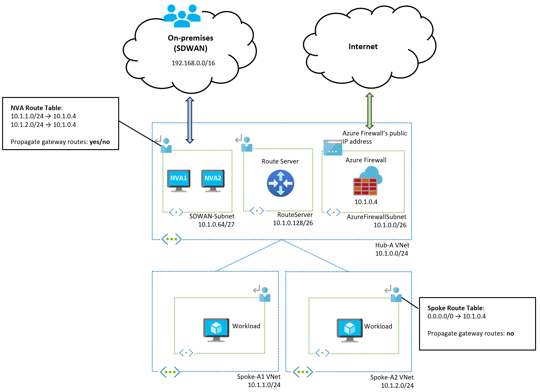
If you use SD-WAN Network Virtual Appliances (NVAs) instead of VPN or ExpressRoute gateways, the design is similar, as shown in the following diagram:
There are different ways to integrate SD-WAN NVAs in Azure. For more information, see SD-WAN integration with Azure hub-and-spoke network topologies. This article shows integration using Azure Route Server, one of the most common methods for routing traffic to SD-WAN networks. The SD-WAN NVAs advertise the on-premises prefixes to Azure Route Server via BGP. Azure Route Server injects these prefixes in the Azure Firewall subnet so that Azure Firewall has routing information for on-premises networks. The spokes don't learn the on-premises prefixes because the "Propagate gateway routes" option is disabled in the spoke route table.
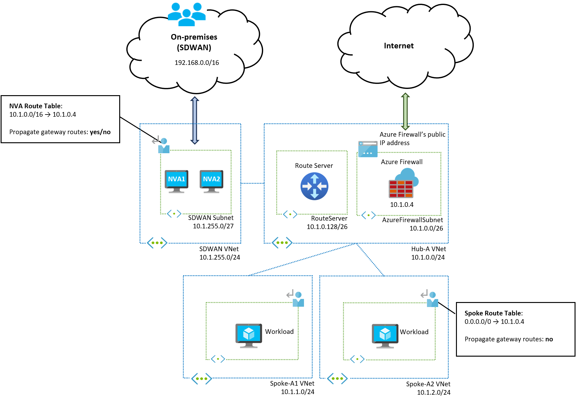
If you don't want to configure each spoke virtual network's prefix in the route table associated with the NVA subnet, you can place the SD-WAN NVAs in their dedicated virtual network. The NVA virtual network doesn't learn the spoke prefixes because they aren't directly peered, and a summary route is possible as shown in the following diagram:
Multi-region hub-and-spoke architecture
After you understand how traffic works within a single hub-and-spoke region, extending the design to a multi-region architecture is straightforward. The following diagram shows an updated network design with hubs in two regions (A and B):
The only addition to the configuration is the route tables associated with the Azure Firewall subnets in each region. Each hub virtual network only knows the prefixes of the directly peered virtual networks, so there's no routing for the prefixes of remote spokes. Add user-defined routes for each Azure Firewall subnet so that traffic for each region is routed to the corresponding Azure Firewall.
In this example, each region can be easily summarized:
- Region A contains prefixes in
10.1.0.0/16 - Region B contains prefixes in
10.2.0.0/16
Defining IP addresses in each region that are easily summarized makes your routing configuration simpler. Otherwise, you need to create one route for each remote spoke.
Enable Propagate gateway routes on the Azure Firewall subnet route table so the firewall can learn on-premises routes from VPN and ExpressRoute gateways.
Note
If Azure Firewall is deployed without a management NIC, the Azure Firewall subnet requires a default route with next hop "Internet" to add more specific routes as previously described.
To simplify the management of user-defined routes in a multi-region environment, you can use Azure Virtual Network Manager. For more information, see Manage user-defined routes across multiple hub-and-spoke topologies with AVNM.
Next steps
- Learn how to deploy and configure an Azure Firewall.
